|
Firing Control Module
A typical firing control module will consist of these main parts:
Firing Contacts
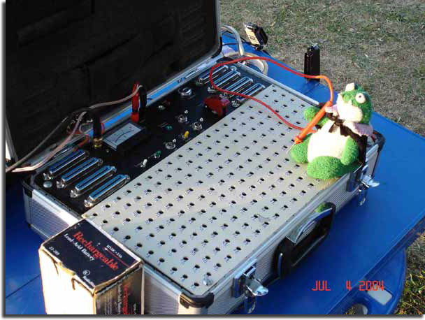
The firing contacts can be in the form of a mechanical switch, a pushbutton, a pin, or a circular metal contact. The mechanical switches are self explanatory. You flip the switch or push the button, you fire a shot. The latter two, pins or circular contacts both use a "Stylus" which resembles a pen. The metal stylus is touched to the pin and/or metal contact corresponding to the shot you want to fire. The pins can be as simple as a nail sticking out of a board. The metal contacts are typically copper or aluminum, and can be coated with solder if desired. The system shown in the picture above is pyroinnovation's legacy 400 shot firing system, and you can see that it uses the circular metal contacts. See Pyrotechnic Innovations's newest firing system.
Battery Interface
Each firing system is battery powered. They can come in different voltages; however, a 24 volt system is very standard. The batteries may be internal or external depending on the system. If the batteries are external, there will be a positive and negative terminal on the control module to attach the battery. Since batteries typically don't come in 24 volt sizes, two 12 volt batteries tied in series are used. Most systems, especially common ground switching systems, require you to hook the batteries up in the correct polarization (positive and negative matter).
 Firing Cable Interface Firing Cable Interface
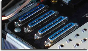
The interface can consist of just a loose cable end hanging out of the firing control module, or more commonly, a connector which sits flush on the firing panel. Depending on the type of firing system and the number of shots available for that particular firing system, you may have a connector with 8 connections or up to 50. See picture to the right.
Ground Terminals
In simplest terms, you must have a path for the electrical current to "return" to the batteries. This is commonly known as "ground". Ground is also sometimes referred to as "common", however, caution must be used with that term when dealing with firing systems, since you could have a "common" positive switching system, which then the "common" now refers to the "positive" portion of the circuit/battery. Some systems are grounded through the firing cables by using some of the wires inside the cable as ground, which gives the advantage of eliminating the need for the operator to worry about grounding the system. The disadvantage to this is that you loose a few cues per cable, thus reducing the overall number of cues your system can fire, and sometimes it can make it difficult to redundantly ground a system. Other systems, simply have ground terminals on each field module, and ground terminals on the firing control module that must be connected via long lengths of wire. This wastes wire and the operators time. A compromise to both types of systems is having a systems similar to the second one described above, with the addition of a wire secured to each firing cable to be used as ground. This way you don't loose any cues, and you don't have to run ground wire each time. Simple, yet efficient. You can download a prinatable copy of the how to ground your firing system that is shown in the electrical grounding video.
Firing Circuit
The firing circuit of your typical analog system will consist of a few arming switches, an indicator light, and a direct path from the batteries to the electric matches you are trying to shoot. Some systems might have a current limiting device to prevent direct "shorts" of the batteries each time they are fired, however, I believe this to be unnecessary since the internal resistance of your firing system and the hundreds of feet of wire that is used provides more than enough resistance to limit the current to a very manageable level. This way, you get the most out of your system, by allowing a higher maximum current flow, you are raising the maximum number of electric matches you can fire per cue, or simply raising the reliability that the amount of current your system is outputting will fire all electric matches on that cue.
Continuity Circuit
The continuity circuit for a firing system is designed to send a very low amount of current through each cue (each electric match) to give you indication that the system "sees" the electric match, and that you have a complete circuit. Continuity systems will typically have a currently limiting device, a switch, and an indicator light/speaker. Depending on the system, different devices can be used to limit the current. You can simply use the appropriate valued resistors inline with the circuit. Other systems could use a simple transistor, sending the current to the electric matches and into the base of a transistor, which then will "turn on" the transistor flowing current to a speaker or light. Make sure you watch our training video on Debugging Continuity Issues.
Take me back to the electrical firing section.
|